Every day, there are more than 45,000 flights carrying 2.9 million airline passengers in the United States alone. While supporting this endeavor, aircraft are subjected to a variety of operational conditions from environmental and human-introduced factors. For example, impacts from hail or tools dropped during repair can weaken the aircraft’s structure. Over time, wear and tear from flights can cause damaged areas to expand and threaten aircraft safety if not monitored.
Not to worry though! Behind the scenes at every major airport is a workforce of inspection and maintenance personnel. Aircraft are regularly pulled out of service for routine maintenance and inspections to detect, monitor, and repair damage to ensure passengers make it safely to their destinations.
Visual inspection is the oldest form of inspection, originating from the early days of the railroad. Usually, this process involves trained personnel who look over the aircraft for small dents and cracks. However, visual inspection is subjective, time-consuming, and cannot confidently detect damage in all cases. Structural health monitoring (SHM) offers a solution to mitigate these issues.
Structural health monitoring involves the implementation of sensors, often mounted to or embedded in the structure, to gather data in situ (while the structure is in service) and monitor changes to the condition of a structure over time objectively and automatically. This allows for quicker and better-informed decisions to be made about maintenance needs to improve safety and reduce the time aircraft need to remain out of service. Our lab at NC State University is developing new structural health monitoring methods to automatically monitor aircraft and other critical structures to supplement or replace visual inspection.
Our recent work on new structural health monitoring technologies is based on computer vision and inspired by the ubiquity of digital cameras in today’s world and their ability to “see” much more than we can. This project seeks to overcome a unique challenge: using cameras to find damage that lies beneath an aircraft’s surface, which would be overlooked by visual inspection. This system would be able to “reveal the invisible” by seeing sub-surface damage that humans cannot.
New Materials, New Challenges
Most structural components in modern, commercial aircraft are made from carbon fiber reinforced polymers (CFRPs), a type of composite material. Composites typically consist of layers of fiber, like carbon fiber, that are adhered together by an epoxy matrix. These materials are lightweight and have higher strength, making them more ideal for aircraft than traditional metallic materials, like aluminum. However, they also pose unique challenges for inspection.
While objects impacting the surface will create visible dents in traditional metallic structures, impact damage in composites usually does not leave a significant dent. Instead, impact damage creates layer separation (delamination) and cracking below the surface. The absence of visible damage on the surface makes inspecting composite structures very difficult since visual inspection cannot reliably detect this barely visible impact damage (BVID). This poses serious safety concerns since a small delamination can significantly reduce the structure’s integrity. To combat this, we are working to develop an inspection system that can reveal this invisible damage.
Measuring Vibrations with Cameras
While it may seem counterintuitive to use a camera to image invisible, subsurface damage, we can do so indirectly by instead recording surface movement caused by guided waves. Guided waves are a special kind of mechanical vibration wave that can travel long distances in thin structures. As these waves emanate from an attached vibrating shaker and travel across the structure, they will interact with any irregularities.
For example, if there is any cracking or layer separation beneath the surface, these irregularities may deflect the wave, or the waves may even become trapped within the damage boundaries. We can use a camera to record the motion of the structure’s surface and look for any reflections or trapped waves caused by damage. By extracting this evidence, we can know the location and approximate size of the subsurface damage.
To extract the motion from a video of the structure, distinct surface features need to be recorded. For this, an artificial speckle pattern is either adhered or painted onto the surface, containing many small, distinct dots. By recording the surface, a video of the speckle motion reveals the surface movement.
Our simple technique for locating damage is based on the premise that damaged areas will vibrate more than healthy regions because waves become trapped within damage boundaries and are amplified. This phenomenon, called resonance, will occur only at specific wave frequencies.
To ensure resonance occurs without knowing any information about the damage in advance, the shaker excites waves over a range of frequencies during the few seconds the surface is being recorded. The damage region is then revealed by adding up all the vibration magnitudes in all frames of the video and plotting these in one final damage image.
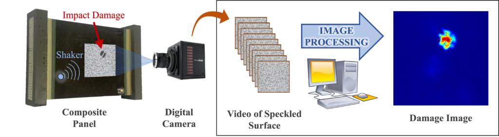
From Surface Video to Damage Image
The process of converting a video of the speckled surface to a single image highlighting the damage beneath the surface involves three steps. First, a filter is applied to keep motion in the video caused by the wave and remove motion coming from other sources, like camera vibrations and noise from the environment. Second, the motion in each frame of the video is correlated with an image representing the time-averaged motion in the entire video. This step isolates motion from waves trapped at the damage location from any other motion. Finally, averaging all of the resulting video frames together produces a single damage image, highlighting locations with local resonance that correspond to the subsurface damage.
To test this technique, we used two composite panels that represent the structure of the fuselage, or main body, of an aircraft. These panels had a 3.7 pound impactor dropped on them from a height of about 5 inches. Even though this may seem like a very minor impact, it created significant damage beneath the surface of the panels. Starting from a mere three-second video of the surface, the process produced clear images revealing the damage hidden beneath the surface (see the image above).
What’s Next?
While the camera-based technique for revealing sub-surface damage is relatively quick and does not require any sensors to be attached to the surface, the need to apply a speckle pattern to the surface currently limits its practicality. To overcome this, we are currently working on a projection-based technique that uses a standard office projector to project a speckle pattern onto the surface to avoid the need to modify the structure’s surface. With the projector at an angle relative to the camera, any surface motion will make the speckles shift within the video.
Once we shift to projected speckles, many future opportunities will be possible. With further research, a similar system could even be mounted on a drone and flown around an aircraft, autonomously mapping subsurface damage over the entire structure. As hardware capabilities continue to grow, we may even be able to pack these inspection capabilities into a smartphone application. Additionally, with the rising interest in reusable spacecraft concepts, similar techniques could help certify used capsules for reuse more quickly.
These technologies will lead to a better understanding of vehicle health and create a safer future for air and space travel. Perhaps one day you may see these robotic inspectors flying or looking around your plane as you wait at the airport terminal.
Dr. Fuh-Gwo Yuan is a recipient of the NC Space Grant Faculty Research Grant and the Samuel P. Langley Distinguished Professor in the Department of Mechanical and Aerospace Engineering at North Carolina State University.
Bryce Abbott has worked with Dr. Yuan on this research since he was an undergraduate at NC State and continues to work with him during his doctoral studies. Abbott is a two-time recipient of the NC Space Grant Undergraduate Research Scholarship and is currently a Ph.D. candidate at NC State studying aerospace engineering.
This post was originally published in North Carolina Space Grant.


